
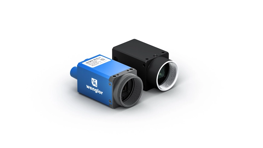
What Is a Machine Vision Camera?
A machine vision camera, also known as an industrial camera, is a key part of a 2D image processing system. Its main function is to capture images, which are then processed by a combination of hardware and software. The information obtained is prepared for various applications.
A typical example of an image processing application in a manufacturing system is quality control, presence control and completeness control. This involves analyzing a specific feature of a part that is produced on an assembly line. In this way, it can be checked whether the part meets the quality criteria or, if necessary, must be sorted out.


Main Components of 2D Image Processing Systems


Lens
Together with the camera and illumination, lenses are crucial to the quality of the images. Lenses enable precise imaging, which not only facilitates the analysis of the finest structures. Choosing the right high-quality lens can optimize both detection and processing time.


The Difference Between Machine Vision Cameras and Smart Cameras
Machine Vision Cameras
Image evaluation takes place via the machine vision controller and the image processing software
Multiple cameras can be connected to a single machine vision controller
Faster process times thanks to high computing power of the machine vision controller
Suitable for very high resolution inspection tasks
Compact camera design

Applications of Machine Vision Cameras
Position Check

Robot Positioning

Parts Measurement

Quality Control

Presence Check

Process Monitoring

Code Reading

Reliable Solution for Cross-Industry Applications


Automotive Industry
Quality inspection of car interior doors
Quality inspection of engine blocks
Position detection for automated tightening


Electronics Industry
Position check of PCBs
Checking the alignment of components
Inspection of plug connectors and cables


Packaging Industry
Check packages for damage, contamination or missing labels
Label inspection of packaging
Minimum shelf life test on PET bottles


Food Industry
Orientation of beverage cans
Label check on packaging
Tethered cap inspection
This Is the Difference Between Surface and Line Cameras


Line Cameras
| Image capture takes place line by line (movement is necessary to capture the object) |
| Image quality dependent on motion and time of image capture |
| Ideal for applications with moving objects and endless materials |
| High speed |
Operating Orinciple of CMOS Sensors with Global or Rolling Shutter
CMOS image sensors have two exposure methods that control how an image is captured and read. These procedures determine the exposure time and thus the amount of light that is converted into electrons as a value in the camera sensor. A distinction is made between global shutter and rolling shutter:

Global Shutter
| Entire image area is exposed simultaneously |
| Suitable for static as well as dynamic applications |
| No image distortion on moving objects |

Rolling Shutter
| Lines are exposed with a time offset |
| For static applications |
| Image distortions due to fast object movements (rolling shutter effect) |
| Capturing still images |

The Rolling Shutter Effect
 Left: Global shutter, Right: Rolling shutter
Monochrome or Color Camera? Which Do I Use When?
Actual Image

Image Capture with a Monochrome Camera

A monochrome camera can distinguish objects from the background.
Image Capture with a Color Camera

A color camera is able to distinguish objects from each other and from the background.
In industrial image processing, a distinction is made between monochrome and color cameras. Monochrome cameras capture grayscale and focus on the differences in brightness in the image. This makes them particularly suitable for applications that require fine contrasts and details, such as when inspecting surfaces or measuring objects.
Color cameras, on the other hand, can capture color information, allowing them to capture surfaces more accurately. They analyze the entire color spectrum, providing more detailed and versatile image reproduction. This makes them ideal for applications where color plays an important role, such as in product quality control, where color differences can indicate material defects.
What to Consider When Installing Machine Vision Cameras


The Machine Vision Camera Interface
Gigabit Ethernet (GigE)

Fast transfer of large amounts of image data
Easy integration thanks to protocol standard
- Multiple cameras can be operated in a network
It is also possible to connect the machine vision camera via a cable using PoE (Power over Ethernet), which means that both power supply and data transfer take place via a single connection.
Resolution
Frame Rate
Exposure Time
The Right Resolution for Every Application
| Resolution | Accuracy | Examples |
|---|---|---|
| 1.6 MP | Applications that do not require extremely high resolution | Optical character recognition, assembly control, presence check |
| 5 MP | Applications requiring medium level of detail | Inspection of packaging |
| 12 MP | Applications requiring high precision | Inspection of fine mechanical parts |
| 24 MP | Applications requiring very high resolution and attention to detail | Checking PCBs for faulty components |


