


Dados ópticos | |
|---|---|
| Alcance | 12.000 mm |
| Refletor de referência/Película refletora | RQ100BA |
| Menor peça detectável | see Table 2 |
| Histerese de comutação | < 5 % |
| Tipo de luz | Laser focado (vermelho) |
| Comprimento de onda | 655 nm |
| Filtro de polarização | Sim |
| Vida útil (Tu = +25 °C) | 100.000 h |
| Classe de laser (EN 60825-1) | 1 |
| Capacidade Luz externa | 10.000 Lux |
| Diâmetro do ponto de luz | see Table 1 |
| Óptica de lente única | Sim |
Dados elétricos | |
|---|---|
| Fonte de energia principal | 10 ... 30 V DC |
| Tensão de alimentação com IO-Link | 18 ... 30 V DC |
| Consumo de corrente (Ub = 24 V) | < 40 mA |
| Frequência de comutação | 1.000 Hz |
| Frequência de comutação (Modo de velocidade) | 2.000 Hz |
| Tempo de reação | 0,5 ms |
| Tempo de resposta (Modo de velocidade) | 0,25 ms |
| Desvio de temperatura | < 5 % |
| Faixa de temperatura de operação | -25 ... 60 °C |
| Queda de tensão na saída de comutação | < 2 V |
| Corrente de comutação da saída de comutação NPN | 100 mA |
| Corrente residual da saída de comutação | < 50 µA |
| À prova de curto-circuito | Sim |
| Protegido contra troca de polaridade | Sim |
| Proteção contra sobrecarga | Sim |
| Travável | Sim |
| Modo Teach-in | NT, MT |
| Interface de usuário | IO-Link V1.1 |
| Classe de isolamento | III |
| Número de acesso da FDA | 2411239-000 |
Dados mecânicos | |
|---|---|
| Tipo de ajuste | Teach-in |
| Material da carcaça |
Plástico, PBT Latão niquelado |
| Encapsulamento | Sim |
| Tipo de proteção | IP67/IP68 |
| Tipo de conexão | M12 × 1; 4 pinos |
| Weight | 27 g |
Dados técnicos de segurança | |
|---|---|
| MTTFd (EN ISO 13849-1) | 2.817,28 a |
Função de saída | |
|---|---|
| IO-Link | Sim |
| Contato NF NPN | Sim |
| Entrada Teach-in externa | Sim |
Parâmetros de ajuste | |
|---|---|
| Saída |
Sincronização NPN PNP |
| Comutação |
Contato NF Contato NA |
| Outros parâmetros |
Atraso de desligamento Atraso de ativação Modos de operação Histerese Ponto de comutação Luz de emissão Modo Teach-in |
| Todos os outros parâmetros podem ser encontrados na documentação do produto. |
Padrões e certificados |
|---|


|


Tabela 1 |
|||
|---|---|---|---|
| Distância de trabalho | 1,2 m | 6 m | 12 m |
| Diâmetro do ponto de luz | 10 mm | 60 mm | 70 mm |
| Tabela 2 | |||
|---|---|---|---|
| Distância sensor/refletor | 1,2 m | 6 m | 12 m |
| Menor peça detectável | 1 mm | 2 mm | 2 mm |
Diagrama de conexão |
|---|


|

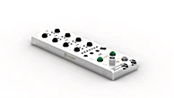
Painel de comando |
|---|


30 = Indicação do estado de comutação/mensagem de sujeira
06 = Tecla Teach-in 68 = Power LED |

Imagem dimensionada |
|---|


Dimensions specified in mm (1 mm = 0.03937")
Parafuso M4 = 0,5 Nm


|


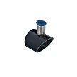
Dados de refletor | |
|---|---|
| RQ100BA | 0 ... 12 m |
| RE18040BA | 0 ... 8 m |
| RQ84BA | 0 ... 12 m |
| RR84BA | 0 ... 11 m |
| RE9538BA | 0 ... 3,5 m |
| RE6151BM | 0 ... 9 m |
| RR50_A | 0 ... 9 m |
| RE6040BA | 0 ... 9 m |
| RE8222BA | 0 ... 6 m |
| RE3220BM | 0 ... 3,5 m |
| RE6210BM | 0 ... 3,5 m |
| RR25_M | 0 ... 5 m |
| RR25KP | 0 ... 1,5 m |
| RR21_M | 0 ... 5 m |
| ZRAE02B01 | 0 ... 3,5 m |
| ZRME01B01 | 0 ... 2 m |
| ZRME03B01 | 0 ... 3 m |
| ZRMR02K01 | 0 ... 2 m |
| ZRMS02_01 | 0 ... 4 m |
| RF505 | 0 ... 2 m |
| RF508 | 0 ... 2 m |
| RF258 | 0 ... 2 m |
| ZRAF08K01 | 0 ... 2 m |
| ZRDF03K01 | 0 ... 7 m |
Produtos complementares |
|---|
|


 Photoelectronic Sensors in R Design
 您有什么问题吗?