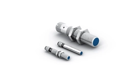
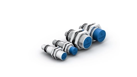
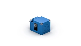
How Inductive Sensors Work


Inductive sensors detect metallic objects contactlessly and measure the distance between the sensor and the object to be measured by electromagnetic induction. To do this, a current is conducted through a coil, creating an electromagnetic field around the coil. If an electrically conductive object such as steel or aluminum approaches the magnetic field, this is changed. The inductive sensor recognizes the change in the magnetic field and evaluates it to determine whether there is a metallic object in the vicinity.
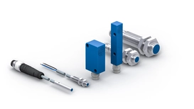
Various Switching Outputs
A signal is present on the digital switching output as soon as the sensor has detected an electrically conductive object. The distance can be output via an analog output as a proportional voltage signal – either as a current value of 4 mA…20 mA or as a voltage value of 0 V…10 V. In the case of inductive sensors with an IO-Link interface, the switching outputs (NPN, PNP or push-pull) can be configured as normally closed or normally open contacts as well as the switching distances.
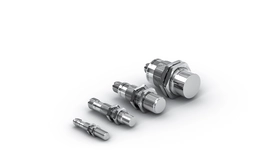
Switching Distances with Inductive Sensors


Correction Factor 1
Influence of Different Materials on the Switching Distance


Switching Frequency for Inductive Sensors


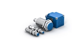
Installation Situations of Inductive Sensors


Flush Sensors


Non-Flush Sensors
weproTec and Alternative Frequency