


Optical Data | |
|---|---|
| Working Range | 200 ... 100,000 mm |
| Measuring Range | 200 ... 100,000 mm |
| Reference Reflector/Reflector Foil | RF505 |
| Reproducibility maximum | 20 mm* |
| Linearity Deviation | 50 mm* |
| Light Source | Laser (red) |
| Wavelength | 660 nm |
| Service Life (T = +25 °C) | 100,000 h |
| Laser Class (EN 60825-1) | 1 |
| Beam Divergence | < 2 mrad |
| Max. Ambient Light | 25,000 Lux |
| Light Spot Diameter | see Table 1 |
| Reflector required | yes |
Electrical Data | |
|---|---|
| Supply Voltage | 18 ... 30 V DC |
| Current Consumption (Ub = 24 V) | < 60 mA |
| Measuring Rate | 50 /s* |
| Measuring Rate (max.) | 100 /s* |
| Temperature Drift | < 0.4 mm/K |
| Temperature Range | -40 ... 50 °C** |
| Analog Output | 4...20 mA |
| Short Circuit Protection | yes |
| Reverse Polarity Protection | yes |
| Overload Protection | yes |
| Interface | IO-Link V1.1.3 |
| IO-Link Baud Rate | COM3 |
| Protection Class | III |
| FDA Accession Number | 2412451-000 |
Mechanical Data | |
|---|---|
| Setting Method | Menu (OLED) |
| Housing Material | Plastic, ABS |
| Optic Cover | Plastic, PMMA |
| Degree of Protection |
IP67 IP68 |
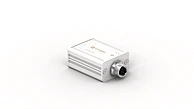
| Connection | M12 × 1; 5-pin |
| Weight | 45 g |
Safety-relevant Data | |
|---|---|
| MTTFd (EN ISO 13849-1) | 353.85 a |
Output | |
|---|---|
| PNP NO | yes |
| Analog Output | yes |
| IO-Link | yes |
Adjustable parameters | |
|---|---|
| Output |
Error Output Warning output |
| Other parameters |
Off-delay On-delay Sensitivity Filter Unit of measure Measuring mode Emitted light Sensor localization Teach mode |
| All other parameters can be found in the product documentation. |
Standards and certificates |
|---|


|


* Depends on mode, see table 2
** At max. 10,000 lux ambient light and min. 500 ohm load at analog output
** At max. 10,000 lux ambient light and min. 500 ohm load at analog output
Table 1 |
|||
|---|---|---|---|
| Working Distance | 0 m | 50 m | 100 m |
| Light Spot Diameter | 5 mm | < 100 mm | < 200 mm |
Table 2 |
|---|


|
Connection Diagram |
|---|


- = supply voltage 0 V
+ = supply voltage + E/A1 = programmable input/output / IO-Link E3 = input O = analog output |

Ctrl. Panel |
|---|


68 = Power LED
5a = Switching Status Indicator, A1 20 = Enter key 60 = display 7c = Analog Output Indicator, O |

Dimensioned Picture |
|---|


Dimensions specified in mm (1 mm = 0.03937")
1 = Transmitter Diode
2 = Receiver Diode
Screw M4 = 0.5 Nm
|

Reflector data | |
|---|---|
| RQ100BA | 0.2 ... 50 m |
| RE6151BM | 0.2 ... 20 m |
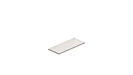
| RF505 | 0.2 ... 100 m |
| RF508 | 0.2 ... 25 m |
| RF258 | 0.2 ... 10 m |
| RF100100 | 0.2 ... 50 m |
| RF5050 | 0.2 ... 25 m |
| ZRAF07K01 | 0.2 ... 100 m |
| ZRAF08K01 | 0.2 ... 100 m |
| ZRDF03K01 | 0.2 ... 25 m |
| ZRDF10K01 | 0.2 ... 50 m |
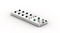
Complementary Products |
|---|
|


 Laser Distance Sensors Time-of-Flight


 Any questions?